Factors to Consider While Creating a Battery Management System.
(Battery Management System)
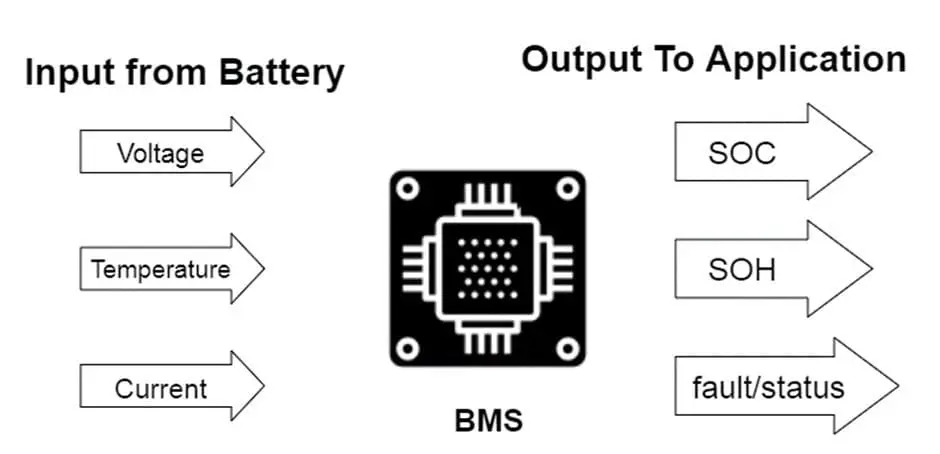
A battery pack electrically arranged in a row x column matrix configuration, is monitored by a BMS, which is a technology designed to provide an appropriate range of voltage and current for a set period against anticipated load scenarios.
In this context, “battery” refers to the complete pack; nevertheless, the responsibilities of monitoring and control are focused on individual cells or groups of cells termed modules within the battery pack assembly. Since they offer the maximum energy density, lithium-ion rechargeable cells are frequently used as the standard option for battery packs in consumer electronics like laptops and electric cars.
To ensure a secure and informative user experience, the BMS is also responsible for giving an accurate state-of-charge (SOC) and state-of-health (SOH) estimation throughout the battery’s lifespan.
Essentials to creating a successful battery management system
By considering all suggestions, you can create an effective battery management system:
Keeping an eye on the battery’s condition
Several factors determine the health of a battery, but its terminal voltage, charge capacity, and cell temperature are the most crucial. Thus, it is necessary to monitor these parameters to monitor battery management systemhealth regularly.
Voltage monitoring
As the name implies, a battery is made up of separate electrochemical cells connected either in parallel or series. Thus, monitoring of each cell voltage is also necessary.
Charge capacity monitoring
When thinking about cell health, the cell’s charge capacity comes first. The intriguing aspect of charge capacity is that it is somewhat reflected in the cell’s terminal voltage for the majority of chemical reactions.
Li-ion cells exhibit a very flat shift in terminal voltage about their charge capacity. This indicates that a decrease in charge capacity has little effect on the terminal voltage. As a result, depending just on the terminal voltage, it is impossible to accurately compute the depth of discharge (DoD) or state of charge (SoC) degrees along their charging/discharge curve.
Cell temperature monitoring
It’s also important to keep an eye on the cell temperature of the battery management system. The intercalation and electrochemical processes within a cell are influenced by its temperature. Overly high cell temperatures can cause a thermal runaway breakdown in Li-ion cell compositions and gasification in lead-acid cells. A Li-ion cell can sustain permanent damage from an extremely low temperature.
Controlling charging and discharging
The main procedure that a battery undergoes is charging and discharging its cells. Maintaining control over the charging and draining process helps to extend the battery’s lifespan. But this form of control is primarily an on-off control.
The battery control system regulates the discharge rate by restricting the discharge current as it does not influence the load that is attached to the battery, which is the main factor in discharge. Likewise, the BMS can only regulate the charging pace by capping the charging current; it has no control over the charger capacity. When the charge or discharge current exceeds the designated maximum value, the battery control system essentially remains transparent to charge movement. At that time, it engages and separates or reconnects the power supply or source from the battery.
Reporting battery condition
One of the BMS’s key functions is to report the battery’s current condition. The most basic battery control system uses LED-based indicators to visually convey the battery’s status of charge. A screen or touch-screen interface may be present in certain advanced BMSs. This enables the user to quickly configure the BMS characteristics at the time of battery connection in addition to monitoring the BMS’s live parameters. For most stationary applications, this is sufficient.
When a battery control system is used in an industrial setting, it can read and write variables to an external supervisory control unit using a simple protocol like MODBUS and the RS232 or RS485 physical bus. Others might let this data be shared via Bluetooth (so your smartphone can monitor the battery through an app) or provide access to it via IP networks, using Wi-Fi or standard Ethernet connectors.
The main electronic control unit (ECU) of the car will anticipate the bms battery management to make all pertinent information available in a recognised digital form if the battery is being used in any kind of electric vehicle. The CAN bus is the most widely used data communication protocol in the automotive industry. Consequently, it could be necessary for the BMS to provide its data via the CAN bus. Using the same connection, the BMS may also be configured with all of its parameters.
BMS fire protection
If a battery, system, or inflammation, the system needs to alert you and take fast action to halt the process. Your bms battery management should have an effective fire safety system in place for that. But there are some things that you can’t always control. For instance, self-ignition may result from manufacturing errors (like defects in the battery plate or cell packaging).
Analyse the structure, parts, and packaging of the battery. Li-ion batteries can be protected from heat loss and short circuits by separators and flame retardants.
The combustion of Li-ion batteries releases harmful fumes, smoke, and flames. Install, repair, and store the BESS correctly, and keep an eye on the voltage, current, and temperature restrictions to prevent this. Smoke detectors can be used to monitor bms battery management combustion and activate fire suppression and cell cooling mechanisms.
Increasing the precision of state-of-charge (soc) and state-of-health (soh)
Providing a correct computation for the battery pack’s SOC and SOH is the primary objective when creating an accurate bms battery management. The use of a pricey AFE with exact cell voltage measurement tolerance may seem like the only option to accomplish this for BMS developers, however, this is only one aspect of the overall calculation accuracy. The fuel gauge cell model and fuel gauge algorithm are the most crucial elements, followed by the AFE’s capacity to provide a synchronous voltage-current readout for cell resistance computation.
AFE direct fault control
Protection management is the primary function of the AFE in the bms battery management. When a malfunction is identified, the AFE can directly regulate the protection circuitry, safeguarding both the battery and the system. Some systems use the MCU for implementing fault controls, however, this increases firmware complexity and causes the MCU to use more resources and respond more slowly. To find any problem conditions, advanced AFEs leverage user setups and their ADC readings. To provide real hardware protection, the AFE responds to errors by opening the protective MOSFETs. Additionally, AFEs are thoroughly tested, which makes ensuring a reliable safety system easy. The MCU can be utilised in this manner to provide an increased degree of safety and resilience as a secondary protective mechanism (battery management system).
High-side vs. Low-side battery protections (Battery Management System)
The placement of the circuit breakers for battery protection should be taken into account while building a bms battery management system. Because N-channel MOSFETs provide a lower internal resistance than P-channel MOSFETs, these circuits are typically built using N-channel MOSFETs. The circuit breakers have the option to be positioned on either the positive or negative terminal of the battery.
By keeping the ground (GND) consistently referenced, high-side architectures help to prevent possible safety and communication problems in the event of short circuits. Furthermore, a stable, clean connection to GND minimises reference signal variations, which is essential for accurate MCU functioning. (Battery Management System.)
Conclusion
To safeguard the battery and the rest of the system, the BMS keeps an eye on the battery pack. A poor BMS not only decreases system safety but also offers incorrect battery SOC management. These errors have a substantial impact on the final quality of the product since they may lead to defects that are hazardous or that degrade the user experience. If you have more questions, get in touch with Variate Solar.